CASE STUDY · DRG-SOL-001

A jounce bumper, taken from sketch to certificate.

One automotive suspension bumper — cast in PU 72 ShA — carried through all six Croslynk stages. This page shows the real numbers at every step: the spec, the simulation, the mold, and the machine data that proved the part.

0
N/mm target stiffness (0–27 mm)
0 mm
free height · Ø41.2 top / Ø55 base
0 kN
full-bound load
0%
elongation at break
01 · DESIGN INPUT

The customer handed us a curve, not a part.

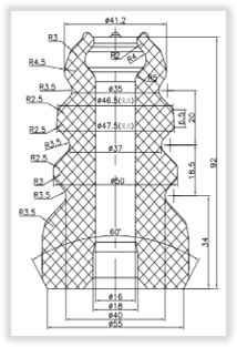
The requirement arrived as a load–deflection envelope: linear 21.4 N/mm over the first 27 mm of travel, staying under 5,038 N at 43.2 mm (bound 2G), and surviving full bound at 46,802 N without damage. Envelope: Ø41.2 mm top seat, Ø55 mm base, 92 mm free height.

Our design study set the waisted profile and convolutions that shape that progressive rate — soft entry, controlled ramp, sharp rise near bottom-out.

RequirementValue
Linear stiffness (0–27 mm)21.4 N/mm
Bound 2G @ 43.2 mm< 5,038 N
Full bound46,802 N
EnvelopeØ41.2 / Ø55 × 92 mm
Engineering drawing DRG-SOL-001 of the jounce bumper
02 · MATERIAL & SIMULATION

PU 72 ShA, proven virtually before any steel was cut.

Cast polyurethane at 72 Shore A gave the best mix of load capacity, rebound and fatigue life for this duty. Coupon data: tensile 7.25 MPa, elongation 342%.

The profile was iterated in FEA until the predicted curve sat inside the customer envelope — the interactive model on the right shows the stress pattern at working load. Drag it. This is the same in-browser engine you can run on your own part.

  • Progressive rate tuned via waist & convolution geometry
  • Stress concentration held below compound limits at bound 2G
  • Mold shrinkage compensated in cavity dimensions
FEA PREVIEW · PU 72 ShA · working load…
drag to orbit · scroll to zoom
Illustrative closed-form FEA — full solver runs are part of the paid stage.
03 · TOOLING & CASTING

Mold cut in-house, cast in-house.

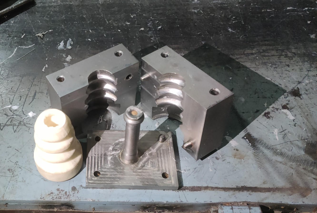
CNC-machined casting mold for the jounce bumper

The two-part casting mold was CNC-machined on our own floor — cavity polished, vents and risers placed for bubble-free hot casting. Because tooling and molding share one roof, the loop from “simulation says change the waist by 0.4 mm” to a revised cavity is days, not weeks.

ItemDetail
Mold typeOpen-cast, 2-part, single cavity
ProcessHot-cast PU, oven post-cure
First articleDimensional + hardness verified
04 · TESTING — THE PART EARNS ITS CERTIFICATE

Measured on our 50 kN UTM, against its own prediction.

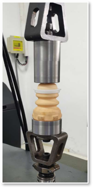
Compression testing on the in-house UTM traced the full load–deflection curve; the measured points landed inside the customer envelope on the first article.

DeflectionSpec / envelopeMeasured
20 mm~428 N (21.4 N/mm line)520 N ✓
43.2 mm< 5,038 Nwithin envelope ✓
59 mmprogressive zone13,000 N ✓
Full bound46,802 N, no damagepassed ✓

Every production batch since ships with hardness, dimensional and stiffness checks — the same data loop that keeps our simulations honest.

Jounce bumper under compression test on the Croslynk 50 kN UTM

Your part could be the next case study.

Bring a drawing, a curve, or just a problem. We’ll take it through the same six stages — and hand you the data that proves it.

Get an instant quote → Watch this part animated in 3D