DESIGN & SIMULATION · ONE PAGE, ONE TEAM

Design & Simulation

We design your rubber or polyurethane part and prove it on screen before any steel is cut.
NONLINEAR FEAHYPERELASTIC FITMOULD-READY CADTEST-CORRELATED
16Design & simulation services
3Hyperelastic models fitted
45A–75DHardness range we design in
1 : 1Every model closed to a test
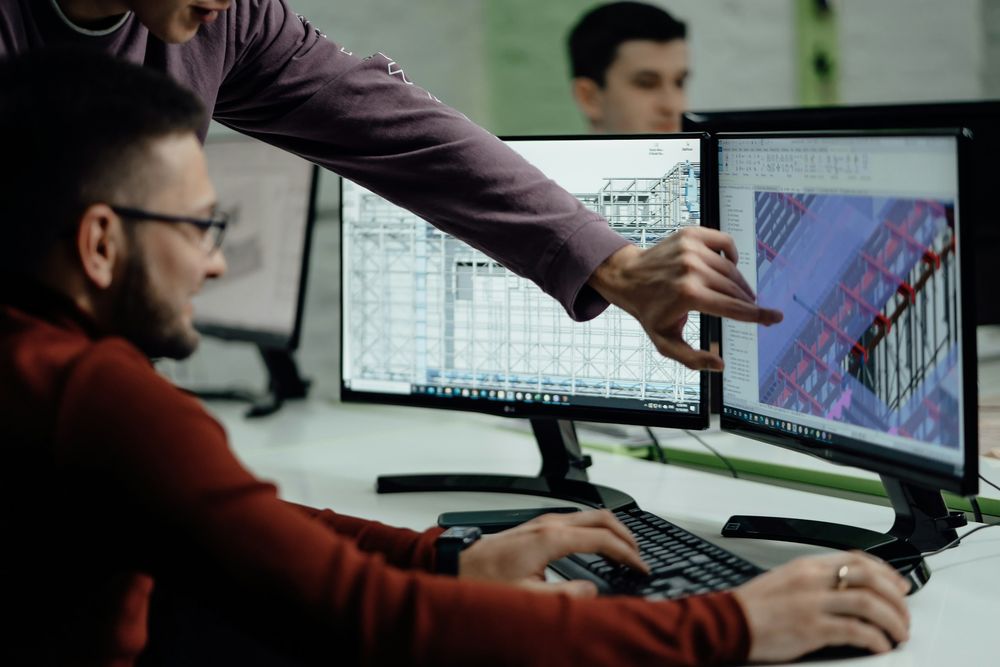
Two engineers reviewing a 3D structural model on a workstation monitor Simulation-led design
THE PROBLEM WE SOLVE

Rubber is non-linear. Design it that way.

Sized like steel, an elastomer part gets the wrong stiffness and fails on the rig, after the tool is cut.

  1. The tool becomes the design reviewEvery change costs steel.
  2. Stiffness misses the targetThe part passes inspection and fails the load test.
  3. Cracks appear on the rigEarly failure on the rig, or in service.
  4. Approval stallsNo evidence, no approval.

Same part, two routes

The mould is the most expensive thing to change. We move the design loops in front of it.

Rule-of-thumb routeLoops in steel
Drawing→Cut tool→Mould trial→Rig test→Re-cut tool→Re-test
Simulation-led routeLoops on screen
Load case→CAD→Material fit→FEA→Cut tool once→Rig test ✓

Every model is checked against a physical test.

Fewer tool re-cuts

The first steel cut is the one you keep.

Stiffness you can sign off

Predicted on your compound, confirmed on test.

Evidence for approval

One report your approver can sign off.

Life known before the rig

Weak spots found while it is still a CAD file.

SERVICES

Sixteen services, one design record.

Take one service or the full chain. Add any to your enquiry.

A

Design engineering

From requirement to a drawing you can build.

Concept & product design

Shape, material and hardness chosen for your duty.

3D CAD & manufacturing drawings

Mould-ready 3D models and drawings.

Design for manufacture

Checked with the tool room before steel is cut.

Reverse engineering & redesign

A sample becomes a drawing you own.

B

Simulation & analysis

The checks your duty needs, nothing more.

Material testing & model calibration

Your compound tested and modelled.

Nonlinear static FEA

Stiffness and strain under real load.

Contact & sealing

Squeeze and contact pressure checked.

Fatigue, durability & compression set

Life known before the rig test.

Dynamic stiffness & NVH

Isolation and damping across frequency.

Bonded metal-rubber & insert integrity

Bond line and insert stress checked.

Impact & drop (explicit dynamics)

Peak force and energy in an impact.

Steel structures & weld fatigue

Castings, frames and welds checked.

C

Validation & reverse engineering

Proof that the design works on the real part.

Failure & root-cause analysis

Why it failed, and the fix.

Test correlation

Model matched to the test result.

Prototype validation

Prototype tested before the mould.

Benchmarking & import substitution

An imported part, matched for local supply.

Physical tests run through the group manufacturing & test facility Croslynk works with. Plant and lab equipment belong to that facility.
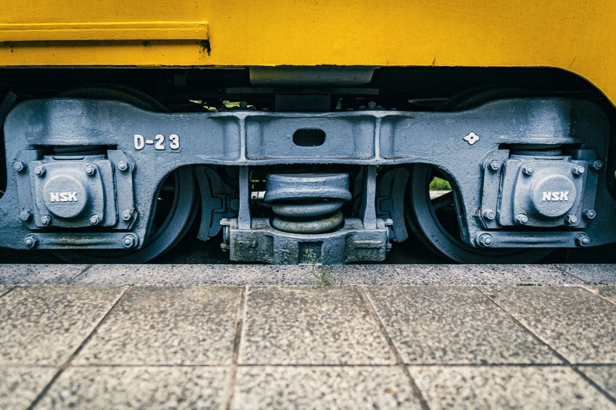
Close-up of a railway bogie with axle boxes and suspension springs

The rubber and the steel around it are one load path. We design and check them together.

BONDED PARTSMOUNTS & BUSHESSEALSSTEEL STRUCTURES
CASE STUDIES

Real results, before the tool was cut.

Three examples below. See all case studies →
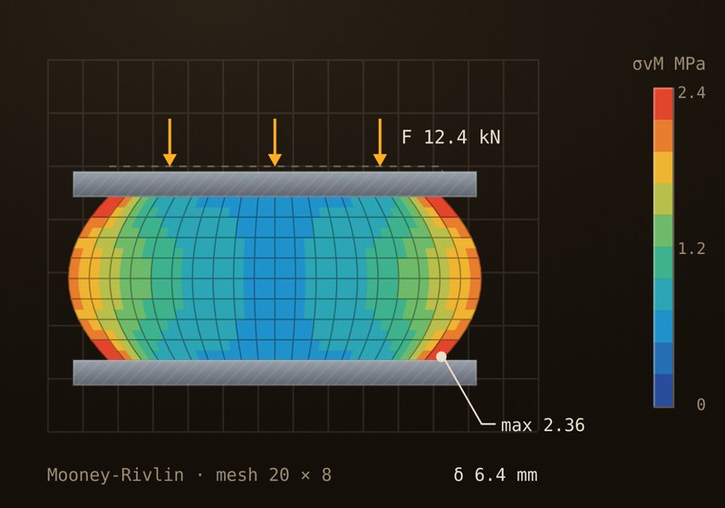
FEA stress contour of a bonded rubber mount under load
FEA output · stress under load
CASE 01 · RAILWAY

Stiffness target met on the first tool

A bonded part for a heavy rail application had to hit a stiffness target before any tool was cut. It did.
On targetStiffness, first time
1stTool cut, kept
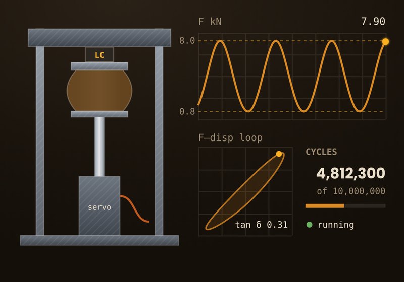
Fatigue rig cycling a polyurethane part, with force trace and cycle count
Fatigue run · force trace and cycle count
CASE 02 · AUTOMOTIVE

Material route chosen on screen

Two PU routes were modelled. The one that met the stroke without bottoming out went to tooling.
2Material routes compared
MillionsOf test cycles passed
Polymer bushes for bonded assemblies
Bonded polymer parts
CASE 03 · ASSEMBLIES

Rubber and steel in one model

Mounts fail where rubber meets metal. Solving both together sized neither part in isolation.

1Model for rubber and steel
TRY IT NOW · SIMULATION EXPERIENCE TOOLKIT

Run a quick FEA in your browser.

Use our demo part or drop in your own STL. Change the load and watch the stress map update. Nothing leaves your computer.

FEAGeometry validation3D viewerMaterial library
FEA · DEMO_PART.STLvon Mises stress
CROSLYNK FEA DEMO
axial compression
units: mm · N · MPa
Upload your own model for a quick FEA
.STL / .OBJ · runs locally, nothing is uploaded to a server
1500 N
60 Shore A
low
high
Request a full simulation →

Demo solver. A simplified estimate for illustration. Paid studies run full nonlinear FEA on your geometry and compound.

Geometry validation

Before any simulation or tooling, every model is checked for manifold integrity, wall thickness and mouldability. Here is the live report for the demo part:

Loading…

What we validate on your parts

  • Watertight / manifold geometry
  • Minimum wall thickness against process limits
  • Draft angles and undercut detection
  • Parting-line feasibility
  • Shrinkage & cure allowance
  • Mesh quality for FEA (aspect ratio, Jacobian)

Interactive 3D viewer

The same viewer powers our Modeling page, where you can upload your own STL/OBJ, inspect it and convert formats for free.

Open the model viewer & converter →

Material library

Typical values used in the demo solver. Real projects use your tested compound.

WAYS TO WORK WITH US

Three ways to engage.

Pick the one that matches where your part is today.

A
You have a drawing or a part

Design review

We check your existing design and tell you what to change.

→ Review report with recommendations
B
You have a load case

Design & simulate

From load case to a drawing ready for tooling.

→ Complete design package
C
You want the part, proven

Design to validated part

Designed, made and tested by one team.

→ Validated part and test report
FAQ

Questions we hear first.

What do you need from us to start?

A drawing helps but is not required. A load, an environment and a target life are enough.

Do you model our compound or a library material?

Your compound, tested and fitted. Without samples we start from typical data and say so.

How long does a study take?

Usually 2 to 4 weeks. Fast-track in 1 to 2.

Is our CAD and IP safe with you?

Yes. We work under NDA from the first call.

Can you also make and test the part?

Yes. Tooling, moulding and testing are all in-house through our group facility.

Do your reports support customer approvals?

Yes. They carry the calculations and test evidence approvers ask for.

START A PROGRAMME

Send us the duty cycle. We send back a design you can prove.

Tell us what you are developing. We reply within one business day with a scoped proposal, stage-wise effort and timeline.

Any one of these starts the conversation

  1. 01
    Drawing or sample2D, 3D, or the worn part itself.
  2. 02
    Load and lifePeak load, stroke, frequency and target cycles.
  3. 03
    EnvironmentTemperature, media, ozone, wet or dry service.
  4. 04
    You receiveMaterial, geometry, tooling route and test plan.
TALK TO THE DESIGN ENGINEER contact@croslynk.com No. 642, 6th Cross, Basaveshwarnagar, Bangalore 560079
Services you need
A · Design engineering
B · Simulation & analysis
C · Validation & reverse engineering
Attach file
Attach drawing / model / spec
PDF, DWG, STL, STEP, SLDPRT, ZIP

We respond within one business day. Or use the full quote page.

Photographs: Pexels and Unsplash contributors under their free licences, credited on each image. Simulation images: Croslynk programmes and one labelled demonstration model.